Basic Concepts
Akso and its ancestor Axoloti are digital modular synthesizer systems with stand-alone hardware, heavily inspired by conceptually similar systems that began to appear in the late 90s. The first key component of such a system is a visual software environment or patcher in which objects are connected with virtual patch cords to create custom signal processing algorithms or patches. This basic software concept is nothing new and has been explored extenstively in environments like Pure Data. The addition of the second component, the stand-alone hardware, is what makes this style of digital modular system unique.
When patches are deployed to the hardware, the patcher environment becomes optional: the user is no longer tethered to a host machine. The hardware can be permanently deployed in an instrument or installation if necessary.
Design Philosophy
Why do this at all? Digital audio processing is well understood. We have very fast machines. A modern machine can run many plugins without breaking a sweat. There are many very capable DAWs and DSP environments to choose from.
In a word: immediacy. There is something magical about playing a real tactile instrument that can never be replicated with a screen, mouse and keyboard. The screen world is full of too many options and distractions and tedious configuration. Instruments should be pick up and play. The incredible success of the Eurorack scene speaks to this idea. An inspiring instrument design seems to win out over raw processing power.
Instruments should be stable. The absurd, intractable complexity of a laptop and its software makes it a risk on stage. The less untrusted code executing during a live performance the better. Running a traditional embedded system and RTOS rather than a full desktop OS gives us total control of the hardware. The system is small and simple enough that it's reasonable for a single human being to keep track of all the code that is executing and optimize it as needed. It's doing only what is absolutely necessary to process audio efficiently, not answering email, browsing the web, connecting to wifi, etc.
Instruments should be extensible. It should be possible for users to add new features that can be shared with the community. This quality is commonplace in pure software environments but seems to be relatively uncommon in hardware instruments.
Hardware Components and Structure
Akso has standard DSP system components: a processor, a codec (DAC/ADC), memory and IO.
The processor is the STM32H743 running at 480Mhz, an ARM Cortex-M7 device. The H7 offers a significant performance boost over the STM32F4 in Axoloti Core and other DSP devices and modules. In terms of raw manufacturer benchmarks, the performance improvement is about 4x. At a practical level, this translates into more complex patches, more oscillators, more voices, more effects, etc.
The codec is the ADAU1961. By default, it operates at a 48KHz sample rate with 24-bit samples but is capable of running with sample rates up to 96Khz. It's stereo 2in/2out but has some interesting extra features including aux input with bypass and a headphone driver. See the datasheet linked at the bottom of this document for complete specifications.
These components are organized in the usual way: the processor manages IO, computes audio data and exchanges data with the codec. Analog audio signals flow to and from the codec.
Memory and Storage
There are several types of data storage available on the Akso board. The H7 processor provides 2MB of internal flash and 1MB of RAM (864K of normal SRAM and 192K of fast core-coupled memory). The default firmware uses only a small fraction of available flash.
An external 32MB SDRAM chip is also available which is particularly useful for samples and data tables.
In addition to this, a microSD card slot is available with four available data lines. Full details about what card types the interface supports are available in the H7 processor reference documentation (links below). The interface targets MMC spec version 4.51 and SD spec version 4.0.
In practical terms, the mircroSD card is useful for storing patches, audio files and any application-specific data.
Signal Input and Output
Note
This section starts with a bit of theory. If you get lost, jump down to the Implementation subsection.
Background
Akso's signal IO is the most unique part of its design. Axoloti Core and other embedded DSP devices and synthesizers, unless specifically designed as dedicated Eurorack modules, are normally AC coupled line level only, usually with unbalanced interconnects. Akso is intended to be useful both standalone and in a Eurorack context, in the studio and on the stage. In the studio, balanced interconnects are preferred. For a quick jam with other hardware synthesizers or mobile devices, unbalanced line level is fine. In Eurorack, 10V peak to peak signals are required, either bipolar -5V/+5V or unipolar 0-10V, with DC coupled operation for control signals. How do we deal with these conflicting requirements?
Widely available audio codecs tend to be signal supply devices often operating on 3.3V. Input and output signals swing not around zero but around a positive reference voltage, nominally 3.3V / 2 = 1.65V, halfway between the supply voltage and ground. The ADAU1961 is designed with 1V RMS (2.83 peak to peak) signals in mind. It expects to work with signals centered at 1.65V swinging up to 1.65 + (2.83 / 2) = 3.065V and down to 1.65 - (2.83 / 2) = 0.235V.
This kind of design is completely fine for line level operation, but doesn't work at all for CV. Input voltages greater than the supply voltage or below ground will damage the codec; output signals cannot swing beyond what the codec generates natively. The 1.65V DC offset is no problem in an AC coupled application, the shift is handled with a coupling capacitor. For DC coupled operation on the other hand, the offset needs to be added on the way in, so the signal is centered at the codec's reference voltage, and removed on the way out, so the output signal is centered at an appropriate value, usually zero.
If we scale and shift signals appropriately, it's no problem to work within the limitations of the codec. What about balanced interconnects? Luckily the ADAU1961 supports differential input and output natively. It's straightforward to support balanced operation with differential signaling.
Implementation
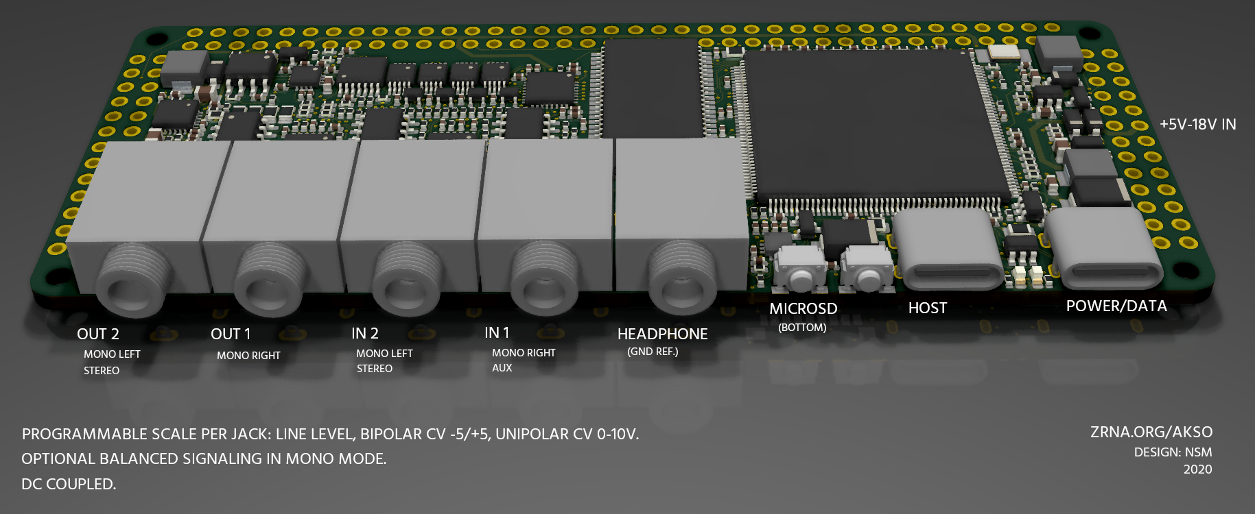
Akso has five 3.5mm TRS jacks. One of these is a dedicated headphone out which is a special case; we'll cover it at the end of this section. The four primary jacks are independently configurable in software and can operate in several modes. Modes control either scale, how signals are scaled and shifted prior to reaching or after leaving the codec, or wiring, how a jack is connected to the codec.
The available scale modes are as follows:
- Line Level
- Bipolar CV -5V/+5V
- Unipolar CV 0-10V
Selecting a scale mode causes a corresponding scale and shift operation in the analog domain outside of the codec. In each case, the codec is operating on signals in its native 1V RMS range.
Wiring modes are unique to each jack:
- Input 1: Mono Right, Aux Stereo
- Input 2: Mono Left, Stereo
- Output 1: Mono Right
- Output 2: Mono Left, Stereo
Stereo modes are unbalanced with the tip mapped to the left channel and the ring mapped to the right channel.
In mono modes, the tip is always the positive polarity signal. For balanced operation, the ring is the negative polarity signal. Mono inputs seamlessly accept balanced or unbalanced connections. Mono outputs have a balanced mode that is optionally enabled in software.
Headphone
The headphone output is driven by a dedicated headphone amplifier capable of driving a 16 ohm load with 25mW. The output is true ground referenced and does not use the codec headphone driver's virtual ground at all. This prevents the potential problem of shorting a virtual ground to ground. This allows the jack to double as an auxiliary stereo line out.
Power
Akso receives power in one of two ways: from its USB-C device port or from its voltage in pin (+5V-18V). These power sources are seamlessly merged together to drive a primary regulator. They can be applied simultaneously and connected and disconnected in any order. For a Eurorack application, power need only be applied at the voltage in pin, either +5V or +12V from your case supply will work.
From this main power input, several power rails are generated, both for internal and expansion use. All generated power rails are available at test points (see the Test Point diagram below). The primary regulator is capable of sourcing 6.5W total to everything downstream. This establishes an ideal upper bound on power available to the system itself and any expansion or peripheral circuitry.
The available power rails and what they drive internally are as follows:
- V, +3.3: Processor, SDRAM, Digital
- +5: USB Vbus Output
- VC, +3.3: Codec, Headphone Amplifier, Analog Switches
- +12: Opamps, Analog Switches
- -12: Opamps, Analog Switches
MIDI
Akso's USB device jack exposes a standard USB-MIDI device to the connected host; it is plug and play with your USB-MIDI setup. The host USB port supports USB-MIDI devices such as keyboards and control surfaces.
Traditional MIDI DIN is also supported at test points but requires a breakout board or adapter. Starting from the voltage in pin VI and working down, the test points align with the five pin connector on Axoloti Core's MIDI section, so it can be reused if you have one available. MIDI RX is mapped to pin G9. MIDI TX is mapped to pin GE.
Software
Akso builds on top of the GPL'd Axoloti project which itself makes extensive use of open source software including ChibiOS and CMSIS. Accordingly, all of Akso's software and firmware is available under the GPL. Objects are generally licensed BSD, but authors are free to license their objects as they see fit.
Akso runs a heavily modified version of the original Axoloti Core firmware that has been altered to run efficiently on the H7 processor. The expectation is that all existing Axoloti objects and any future objects written against Axoloti's API will be compatible with the exception of objects that rely on low level hardware details. The H7 and F4 processors have some differences in peripheral operation and memory layout but are generally binary compatible. Purely mathematical or logical objects work directly without alteration. If you are familiar with developing objects for Core, you will not need to change your approach unless you want to take advantage of H7-specific features. If you find an issue with a specific legacy object, please open a topic on the forum.
Beyond the processor difference, Akso has some new hardware features compared to Core such as its programmable IO modes. These features are accessed through new configuration objects. For example, to configure a particular jack as bipolar CV instead of line level, you simply include a scale configuration object in your patch. The object handles applying the configuration at the hardware level.
Extensibility
Akso is designed to be extended. Most hardware functions, both analog and digital, are available at test points. Theoretically, all of the IO connectors are optional and could be removed for an embedded build.
While Akso currently runs the Axoloti software platform by default, there is nothing preventing the hardware from running completely different software stacks, bare metal code and so on. The hardware can easily be flashed with custom firmware via USB DFU or via SWD with a debugger. Any DSP code that can be ported to bare metal ARM is reasonably straightforward to get running. The longer term goal is to directly support execution of DSP code from as many sources as possible. Given the vast library of open source DSP code available, it makes no sense to limit ourselves to one particular implementation.
This approach also provides a path for commercial product development that may be incompatible with a GPL software stack. A bare metal template project under a permissive license will be provided for this purpose.
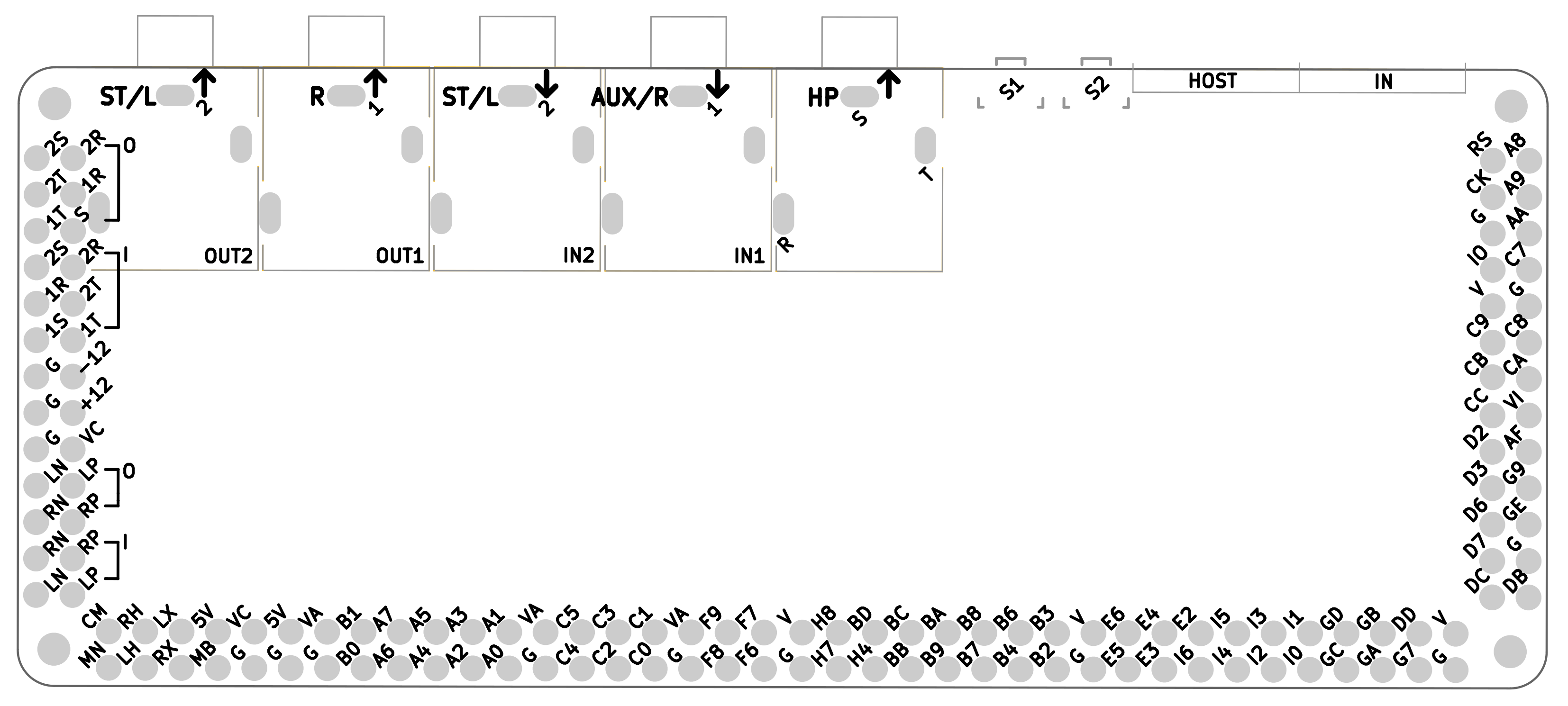
Pinout
🔍 Akso pinout. Bottom view.
Unless specified below, silkscreen pin codes correspond with the H7 processor pin codes. E6 corresponds with PE6 in the datasheet for example. The datasheet is the ultimate reference for what functions are available on each processor pin. Pin numbers higher than 9 are notated in hex to save space, i.e. AA -> PA10, BD -> PB13 and so on. Pin assignments that existed on Axoloti Core have the same definitions by default, e.g. A0 through A7 are ADC inputs.
Top Left, O section
- 1T, 1R, S: TRS Output 1
- 2T, 2R, 2S: TRS Output 2
Top Left, I section
- 1T, 1R, 1S: TRS Input 1
- 2T, 2R, 2S: TRS Input 2
Bottom Left, O section
- LP: codec left output, positive
- LN: codec left output, negative
- RP: codec right output, positive
- RN: codec right output, negative
Bottom Left, I section
- LP: codec left input, positive
- LN: codec left input, negative
- RP: codec right input, positive
- RN: codec right input, negative
Bottom Left
- CM: codec reference voltage, buffered
- MN: codec MONOOUT
- RP: codec right headphone out
- RN: codec left headphone out
- LX: codec left aux input
- RX: codec right aux input
- MB: codec mic bias output
Power:
- V: +3.3V processor/digital
- VA: +3.3V processor ADC reference
- VC: +3.3V analog
- G: ground
SWD, Upper Right:
- RS: processor NRST pin
- CK: SWCLK
- IO: SWDIO
Tactile Switches, Top:
- S1: hold at power on to enter DFU mode
- S2: user switch connected to AA/PA10
Datasheets
STM32H743IIT:
ARM Cortex M7 microcontroller
ADAU1961:
Stereo Audio Codec