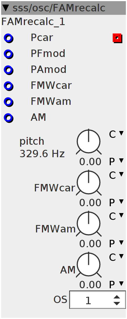
FAMrecalc
This is a FM and AM oscillator in which the modulation frequencies and carrier frequencies are recalculated based upon the "wanted" frequencies set by the pitch inputs. The module can thus play "chords" where the 2nd and 3rd note of the chord are created by FM and AM modulation (and thus also creating overtones based on the FM/AM modulation). The module can be oversampled, although differences in response are hard to hear.
Inlets
frac32 Pcar
frac32 PFmod
frac32 PAmod
frac32 FMWcar
frac32 FMWam
frac32 AM
Outlets
frac32buffer out
Parameters
frac32.s.map FMWcar
frac32.s.map FMWam
frac32.s.map AM
int32 OS
frac32.s.map.pitch pitch
uint32_t Phase[6];
int32_t nF[3];
int32_t fc3;
int32_t S1a;
int32_t S1b;
int32_t S2a;
int32_t S2b;
int32_t S2c;
int32_t S3;
int32_t val;
int i;int32_t fc1a;
MTOFEXTENDED(param_pitch + inlet_Pcar, fc1a);
fc1a = fc1a / param_OS;
nF[0] = fc1a;
// fc1a+=nF[2];
int32_t FMWa = ___SMMUL(fc1a, param_FMWcar + inlet_FMWcar << 4);
int32_t fc1b;
MTOFEXTENDED(param_pitch + inlet_Pcar, fc1b);
fc1b = fc1b / param_OS;
nF[1] = fc1b;
fc1b -= nF[2];
int32_t FMWb = ___SMMUL(fc1b, param_FMWcar + inlet_FMWcar << 4);
int32_t fc2a;
MTOFEXTENDED(param_pitch + inlet_PFmod, fc2a);
fc2a = fc2a / param_OS;
fc2a += fc1a;
int32_t fc2b;
MTOFEXTENDED(param_pitch + inlet_PFmod, fc2b);
fc2b = fc2b / param_OS;
fc2b += fc1b;
int32_t fc2c;
MTOFEXTENDED(param_pitch + inlet_PFmod, fc2c);
fc2c = fc2c / param_OS;
fc2c += nF[2];
int32_t fc4;
MTOFEXTENDED(param_pitch + inlet_PAmod, fc3);
fc3 = fc3 / param_OS;
nF[2] = (nF[1] - fc3) / 2;
fc4 = (fc3 - nF[1]) / 2;
int32_t FMWc = ___SMMUL(fc4, param_FMWam + inlet_FMWam << 4);
int32_t AM = __SSAT(inlet_AM + param_AM, 28);
int32_t MIX = (1 << 27) - (AM > 0 ? AM : -AM);
int32_t Q;
MTOF((1 << 59), Q)
Q = Q / (1 + param_OS / 2);for (i = 0; i < param_OS; i++) {
Phase[0] += fc1a + (___SMMUL(S2a << 3, FMWa) << 3);
Phase[1] += fc1b + (___SMMUL(S2b << 3, FMWb) << 3);
SINE2TINTERP(Phase[0], S1a)
SINE2TINTERP(Phase[1], S1b)
S1a = (S1a >> 4);
S1b = (S1b >> 4);
Phase[2] += fc2a;
Phase[3] += fc2b;
Phase[4] += fc2c;
SINE2TINTERP(Phase[2], S2a)
SINE2TINTERP(Phase[3], S2b)
SINE2TINTERP(Phase[4], S2c)
S2a = (S2a >> 4);
S2b = (S2b >> 4);
S2c = (S2c >> 4);
Phase[5] += fc4 + (___SMMUL(S2c << 3, FMWc) << 3);
SINE2TINTERP(Phase[5], S3)
S3 = (S3 >> 4);
int32_t carrier = ___SMMUL(MIX << 3, S1a << 2) + ___SMMUL(AM << 3, S1b << 2);
val = ___SMMLA(((___SMMUL(MIX << 3, carrier << 2) * 0 + carrier +
___SMMUL(AM << 3, ___SMMUL(carrier << 3, S3 << 2) << 2)) -
val)
<< 1,
Q, val);
}
outlet_out = val;