QO_core
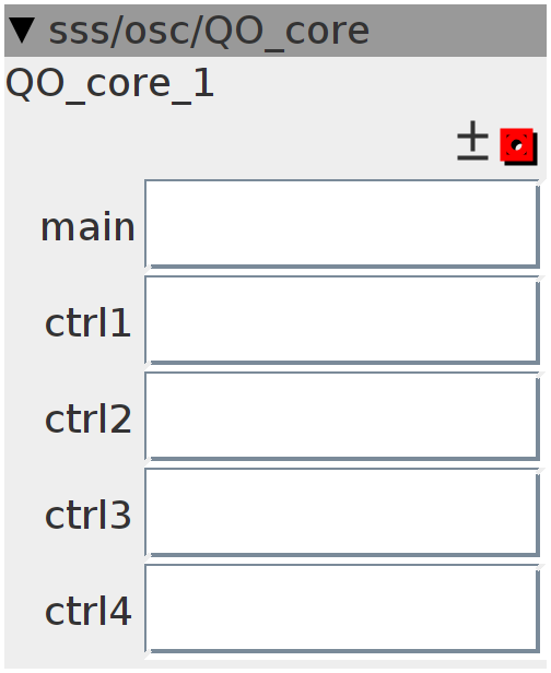
quad core oscillator, controlled by the QO_main and QO_control modules. Enter the name of the QO_main and QO_control modules into the object reference boxes. Also volume (envelope) is controlled by the main and control modules. The overall volume is controlled from the main module The volumes of the seperate oscillators is controlled from the control modules So no need for external vca's
Inlets
None
Outlets
frac32buffer.bipolar sine wave
Attributes
objref main
objref ctrl1
objref ctrl2
objref ctrl3
objref ctrl4
Declaration
uint32_t Phase[4];
uint32_t Phose[4];
int32_t freq[4];
int32_t fraq[4];
int waveform[4];
int32_t r[4];
int32_t volume[4];
int32_t sum;
int i;
int32_t tri;
int32_t FM[12];
int32_t lp[4];
int32_t hp[4];
int32_t cut[4];
int32_t result[4];
int32_t PWM[4];
uint32_t phase[4];
int32_t LFO[4];
int32_t rate[4];
int32_t lpwm[4];
int32_t width[4];
Init
for (i = 0; i < 4; i++) {
  Phose[i] = 0;
}
Control Rate
freq[0] = attr_ctrl1._freq;
freq[1] = attr_ctrl2._freq;
freq[2] = attr_ctrl3._freq;
freq[3] = attr_ctrl4._freq;
waveform[0] = attr_ctrl1._waveform;
waveform[1] = attr_ctrl2._waveform;
waveform[2] = attr_ctrl3._waveform;
waveform[3] = attr_ctrl4._waveform;
volume[0] = attr_ctrl1._volume;
volume[1] = attr_ctrl2._volume;
volume[2] = attr_ctrl3._volume;
volume[3] = attr_ctrl4._volume;
FM[0] = attr_ctrl1._fm1;
FM[1] = attr_ctrl1._fm2;
FM[2] = attr_ctrl1._fm3;
FM[3] = attr_ctrl2._fm1;
FM[4] = attr_ctrl2._fm2;
FM[5] = attr_ctrl2._fm3;
FM[6] = attr_ctrl3._fm1;
FM[7] = attr_ctrl3._fm2;
FM[8] = attr_ctrl3._fm3;
FM[9] = attr_ctrl4._fm1;
FM[10] = attr_ctrl4._fm2;
FM[11] = attr_ctrl4._fm3;
cut[0] = attr_ctrl1.cut;
cut[1] = attr_ctrl2.cut;
cut[2] = attr_ctrl3.cut;
cut[3] = attr_ctrl4.cut;
rate[0] = attr_ctrl1.rate;
rate[1] = attr_ctrl2.rate;
rate[2] = attr_ctrl3.rate;
rate[3] = attr_ctrl4.rate;
width[0] = attr_ctrl1.width;
width[1] = attr_ctrl2.width;
width[2] = attr_ctrl3.width;
width[3] = attr_ctrl4.width;
lpwm[0] = attr_ctrl1.PWM;
lpwm[1] = attr_ctrl2.PWM;
lpwm[2] = attr_ctrl3.PWM;
lpwm[3] = attr_ctrl4.PWM;

for (i = 0; i < 4; i++) {
  phase[i] += rate[i];
  SINE2TINTERP(phase[i], LFO[i])
  PWM[i] = ___SMMUL(___SMMUL((LFO[i] >> 2), attr_main.PWM << 3) << 3,
                    width[i] << 2) +
           lpwm[i];
}
Audio Rate
sum = 0;

for (i = 0; i < 4; i++) {
  fraq[i] = freq[i] + (___SMMUL(freq[i] << 3,
                                (___SMMUL(FM[i * 3], result[(i + 1) & 3]) +
                                 ___SMMUL(FM[i * 3 + 1], result[(i + 2) & 3]) +
                                 ___SMMUL(FM[i * 3 + 2], result[(i + 3) & 3])))
                       << 5);
  // Phase[i] += fraq[i];
  Phose[i] += fraq[i];
  if (PWM[i] >= 0) {
    Phase[i] =
        ___SMMUL(Phose[i], (((1 << 27) - PWM[i]) + ___SMMUL(Phose[i], PWM[i]))
                               << 4)
        << 1;
  } else if (PWM[i] < 0) {
    Phase[i] = ((1 << 32) - 1) - Phose[i];
    Phase[i] =
        ___SMMUL(Phase[i], (((1 << 27) + PWM[i]) + ___SMMUL(Phase[i], -PWM[i]))
                               << 4)
        << 1;
    Phase[i] = ((1 << 32) - 1) - Phase[i];
  }

  //
  if (waveform[i] == 0) {
    SINE2TINTERP(Phase[i], r[i])
  }
  if (waveform[i] == 1) {
    r[i] = Phase[i];
    r[i] = r[i] > 0 ? r[i] - (1 << 30) << 1 : -r[i] - (1 << 30) << 1;
  }
  if (waveform[i] == 2) {
    r[i] = Phase[i];
  }
  if (waveform[i] == 3) {
    r[i] = Phase[i] > (1 << 31) ? (1 << 30) : -(1 << 30);
  }
  lp[i] = ___SMMLA(((r[i] >> 1) - lp[i]), cut[i], lp[i]);
  hp[i] = hp[i] + ((lp[i] - hp[i]) >> 12);
  result[i] = hp[i] - lp[i];
  sum += ___SMMUL(volume[i], result[i]);
}
outlet_wave = ___SMMUL(sum << 3, attr_main._volume << 2);